Evaluating the Contribution of
Large Wind Power Plants on the Fault Current at the Lower Voltage Levels in
Kenya
Eng.
Erick Ohaga, CE, FIEK, AMCIArb, MKIM, MKOSSE,
KENYA
POWER, P.O.BOX 26374-00100 Nairobi KENYA
*Corresponding
author: eohaga@nuclear.co.ke
1 INTRODUCTION
The
Feed in Tariff Policy has stimulated immense interest in the investment on
renewable Energy sources in Kenya over the last 10 years. Each of The
distributed generation and the Large Power plants introduced into the power
system has an integral contribution on the system fault levels at the various
bus-bars voltages. As the capacity of power systems is increasing, the short
circuit current levels are continuously going up. The ratings of system
switchgears and instrument transformers at many existing substations that were designed
many years ago are now becoming underrated with present fault current levels. Such
a situation is great concern to the protection engineers who strive to ensure
that the security and dependability of the protection is not jeopardized.
Besides risks of trivial CT saturation, which affects the security of the
protection system, the major concern is on the effect on the rating of the
existing system switchgears. In Kenya, the relationship between the system
planning departments and system protection has not been symbiotic as is the
case in other developed power system networks in developed countries. In view of
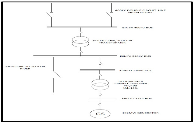
this, a system study has been carried on impact of the 100MW wind-farm
injecting at 220kV at Isinya 400kV/220kV substation in Kajiado County and
suggest mitigating measures on the underlying impacts.
2 METHODOLOGY
The
system was modeled using PSSE software. The system was simulated in the base year
of 2020, 2025 and 2030 to check the levels of fault current at the various 66kV
busbars. The selection of buses under study was based on the distance from the
power plant (one near and one further apart).
 |
| Figure 1: Wind Power connection to Isinya Transmission substation. |
2.1 Three Phase Fault Levels at 66kV bus-bar in 2020
The
following results indicate the maximum three phase fault currents at the 66kV
bus bars
in the event of a fault in the year 2020.
2.2 Three Phase Fault Levels at 66kV bus-bar in 2025
The
following results demonstrate the maximum three phase fault currents at the
66kV bus bars in the event of a fault in the year 2025.
2.3 Three Phase Fault Levels at 66kV bus-bar in 2030
The
following results depict the maximum three phase fault currents at the 66kV bus
bars in the event of a fault in the year 2030.
22.4 MITIGATING MEASURES
2.4.1 Current Limiting Reactor
(CLR)
The
CLR introduces higher impedance to the system by series–connected reactance in
order to protect the equipment during fault condition. It reduces short circuit
level to meet the system needs as well as stresses on busses, insulators, circuit
breakers and other high voltage devices.
2.4.2 Fault Current Limiter (FCL)/BUS
SPLITTING
Fault
current limiter is very quickly capable of detecting and limiting a short
circuit current by use of a small explosive charge to open a conductor. This
diverts the current to a parallel fuse, which quenches the short circuit
current.
3 RESULTS
The
fault levels results indicate that at the lower voltages, the contribution of
the large wind farm has a significant contribution on the short circuit
current. Selecting one busbar near the power plant and another further from the
plant.
4 CONCLUSION
It
is evident that the contribution of large wind-farm on the system fault level
is significant and mitigating measures should be provided by the developers at
the approval stage, so that during the implementation, monitoring and
evaluation is done to ensure compliance.
REFERENCES
[1] GE
publication GET-3550F, Short Circuit Current Calculations, 1989.
[2]
International Renewable Energy Agency, Renewable Energy Capacity Statistics
2015,
[3] IEC
Short circuit currents in three-phase A.C. systems – Part 0: Calculation of currents,
IEC Standard 60909-0, January 2016.
[4] IEC
Short circuit currents – Calculation of effects – Part 2: Examples of
calculation,
IEC
Technical Report 60865-2, April 2015.
[5]
Ontario Energy Board, Transmission System Code, August 2013.
[6]
FiT application and applications Guidelines- Final copy 2015


No comments:
Post a Comment